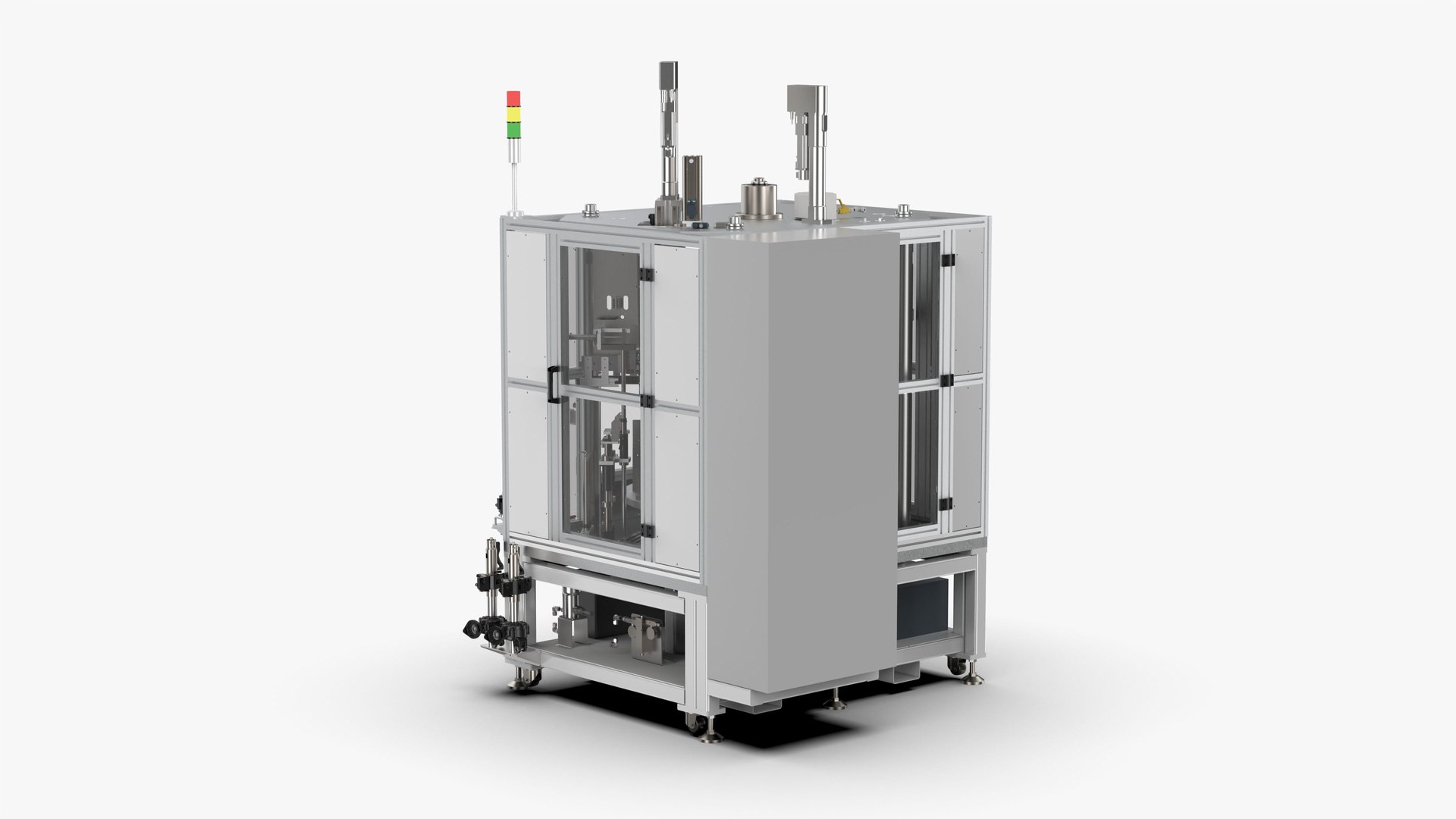
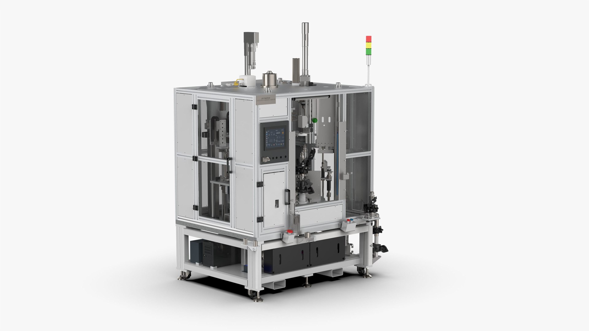
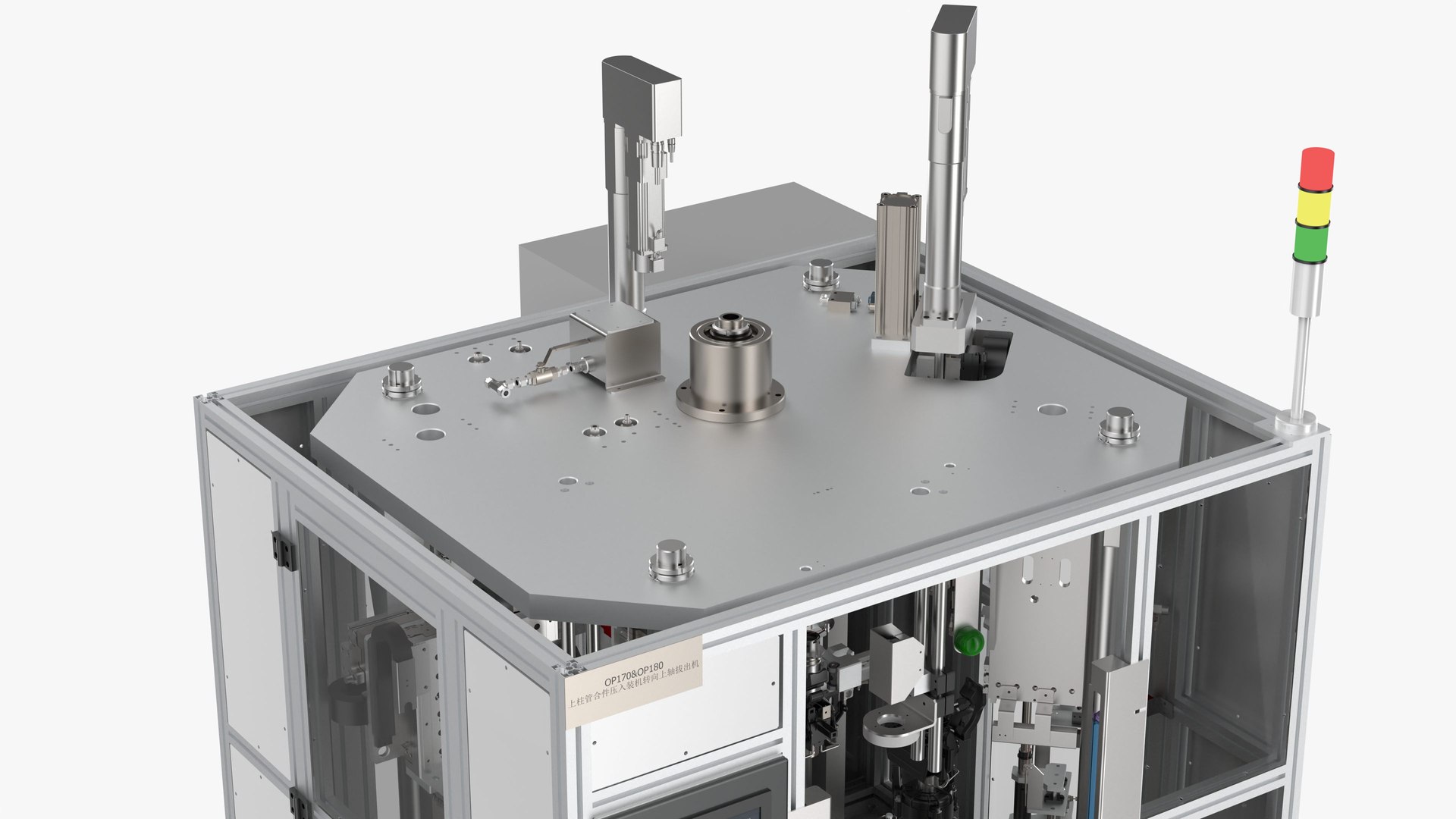
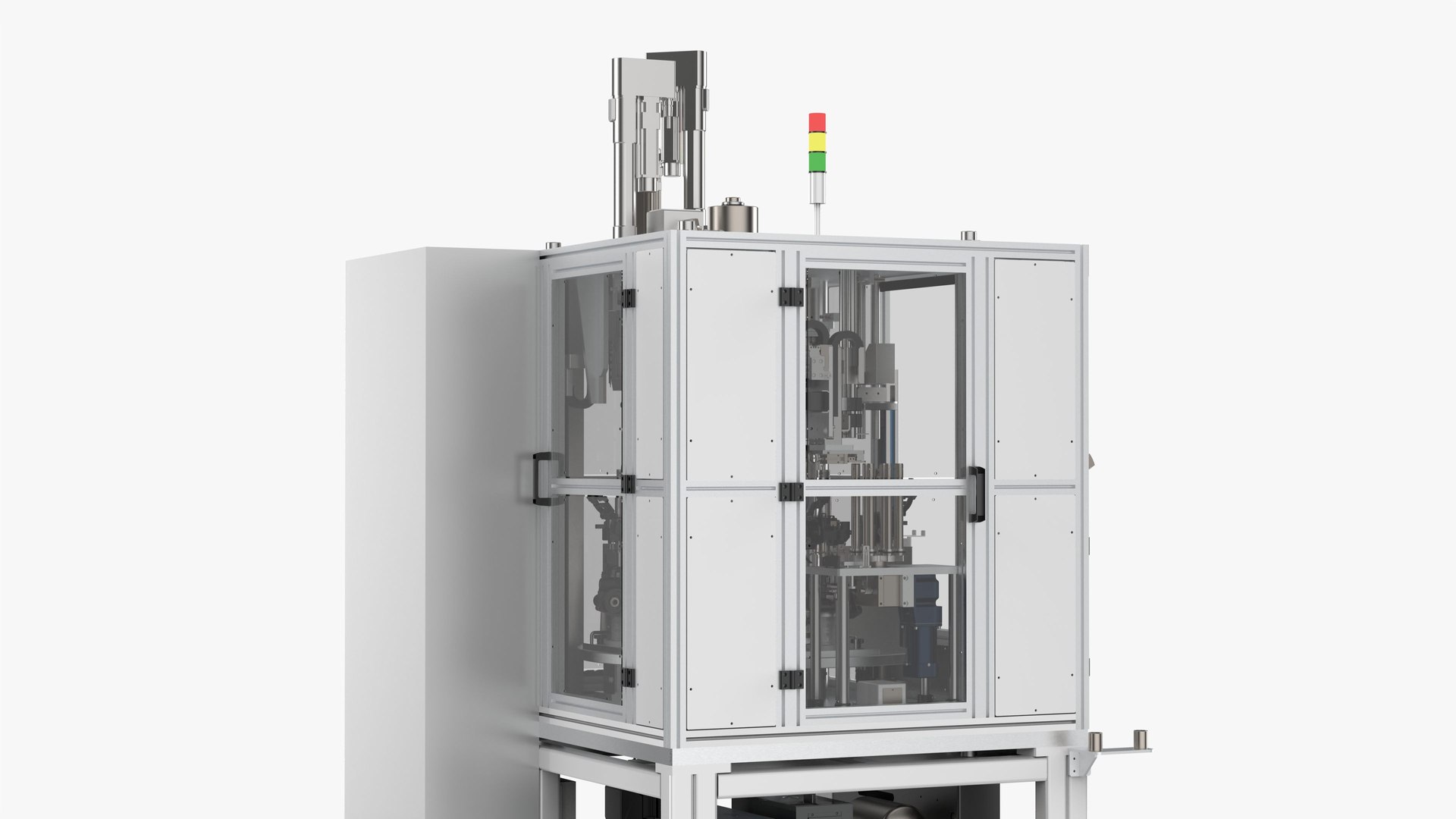
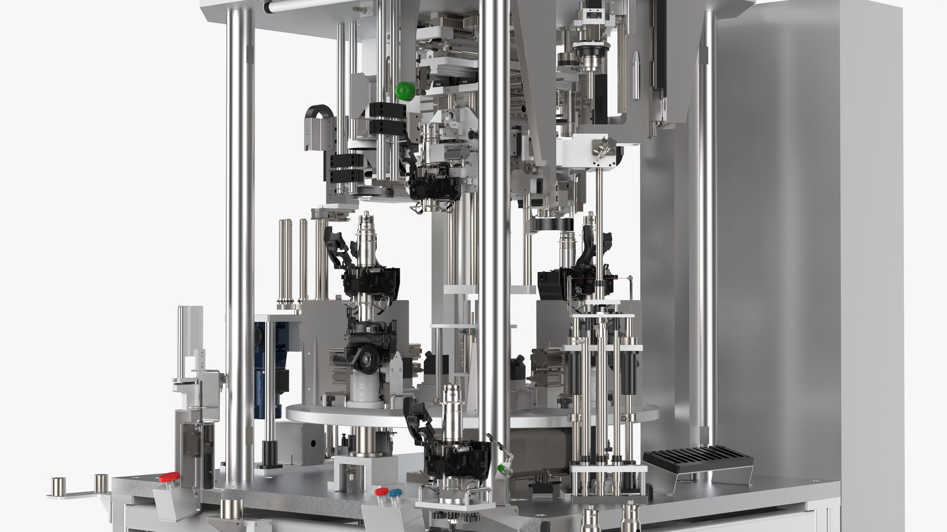
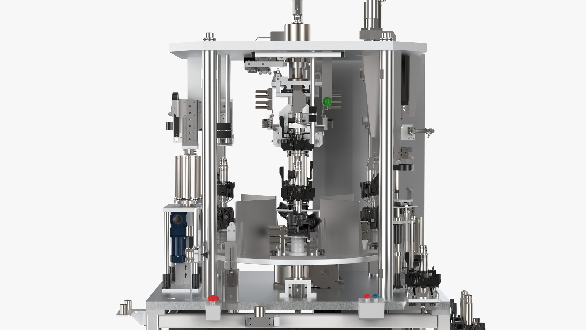
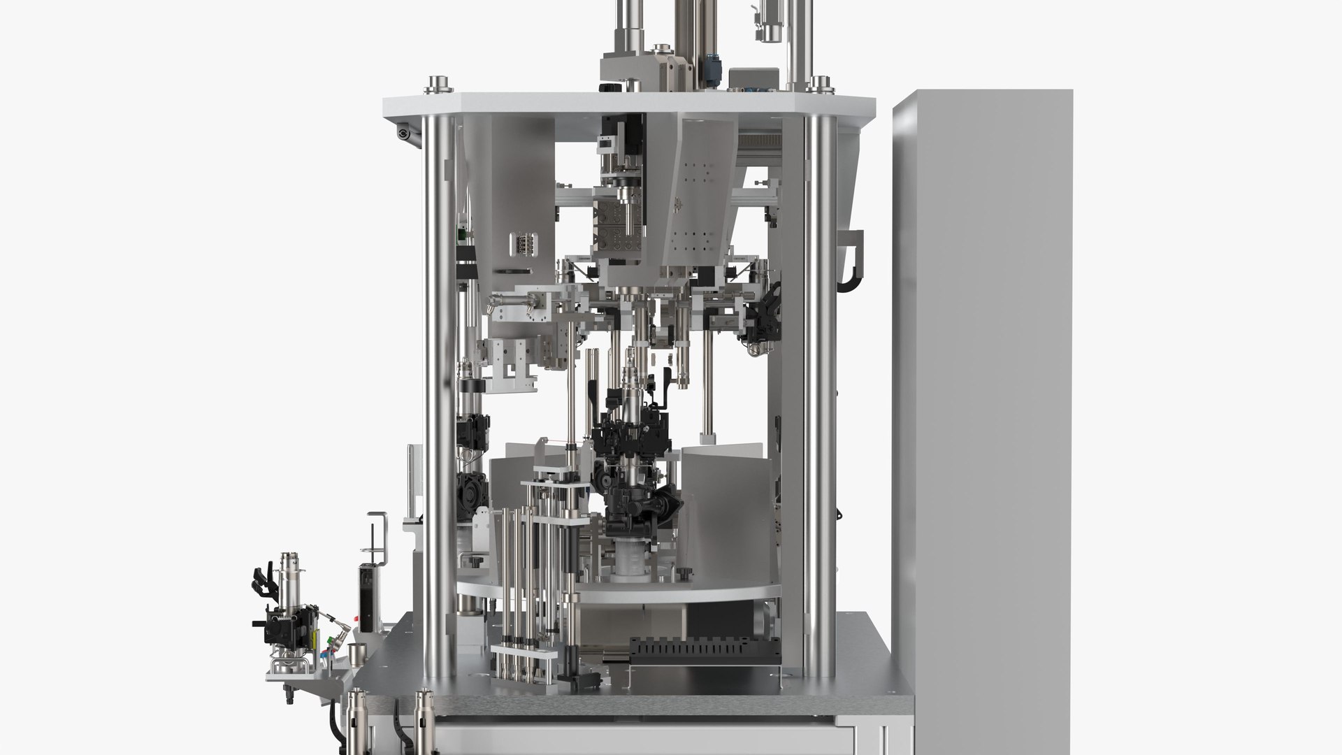
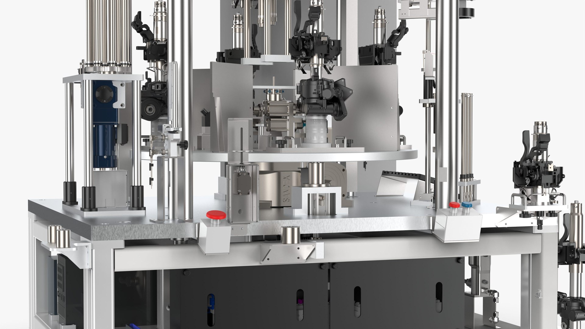
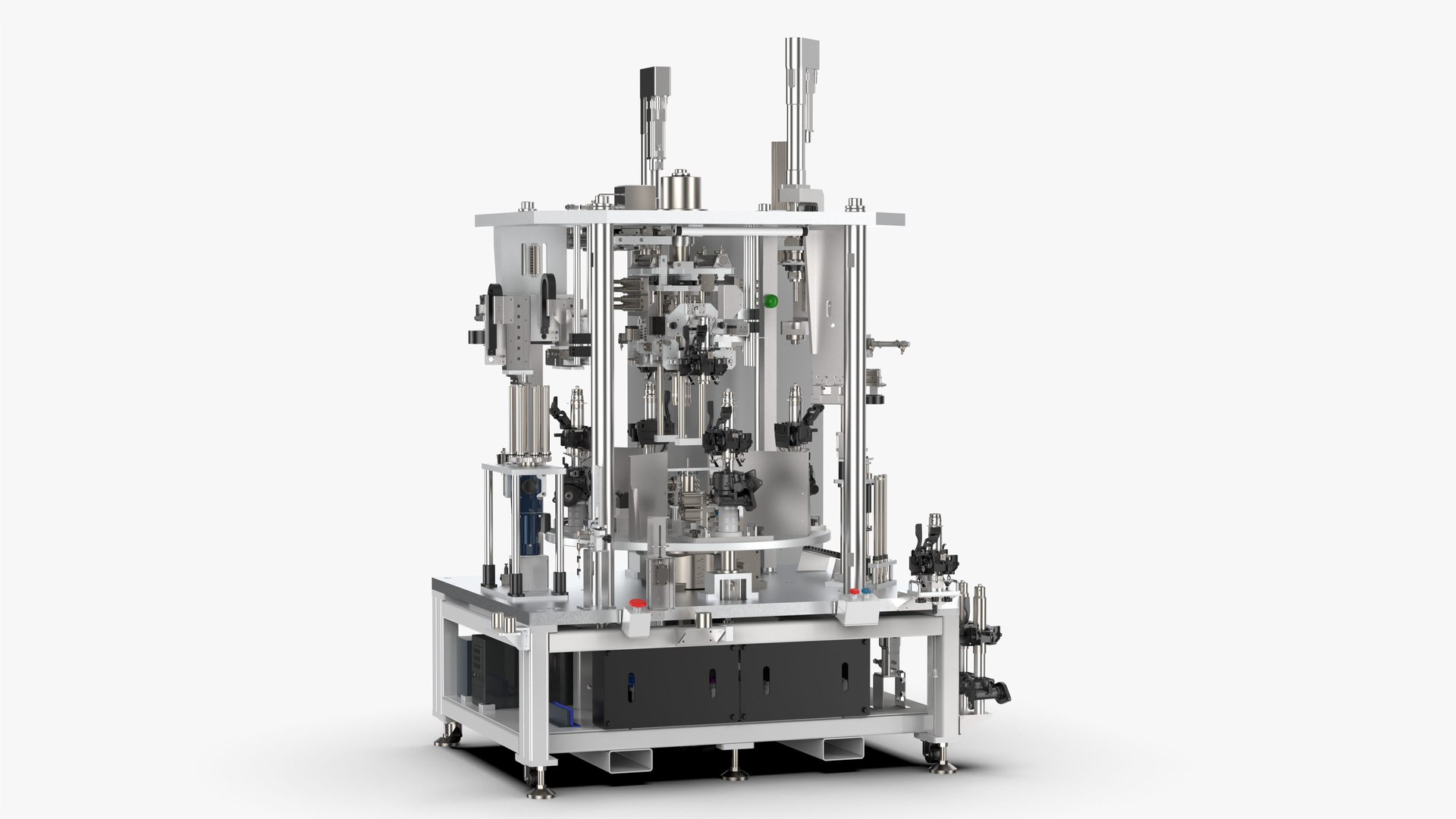
Introduction
Equipment operation process (50s)
STA0 (28s)
1. Take the upper column tube and place it in the oiling station for automatic oiling (2s)
2. Take the gearbox assembly Put it on the circlip installation jig and install the circlip manually (14s)
3. Scan the oiled upper column tube and install it in the automatic equipment (6s)
4. Scan the workpiece with the lower circlip installed In automatic equipment (6s)
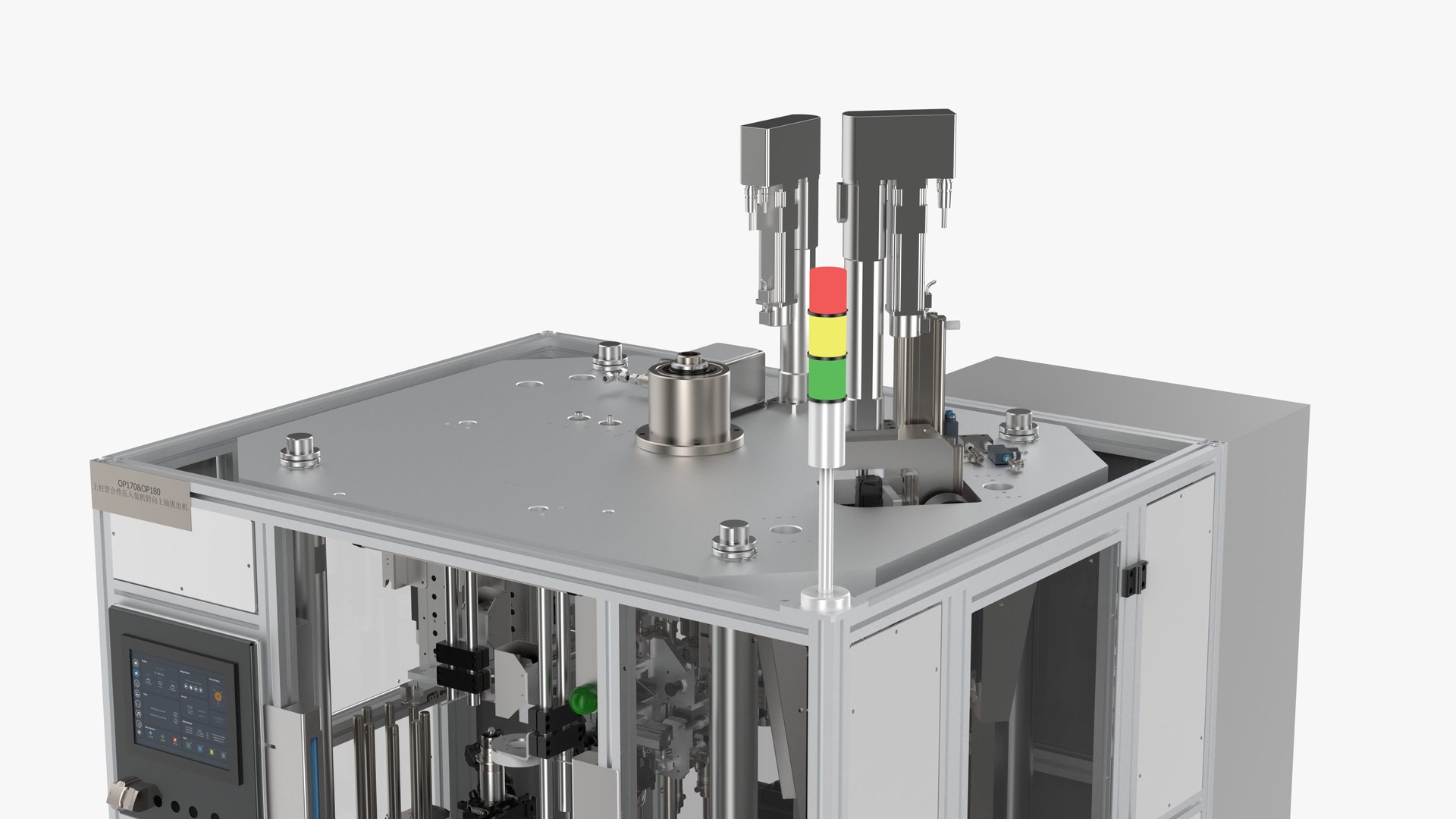
STA1 (17s)
1. Manual feeding (manual 3s)
2. Take the pipe string assembly and put it into the lower clamp on the turntable (3s)
3. Take the oiled upper pipe string, loosen Open the handle and put it on the positioning fixture (4s)
4. The fixed-phase pressing cylinder presses the adjustment bracket (automatically 1s)
5. The pipe string straightening cylinder pushes the inclined pipe straight (due to the spring force) (automatically 1s)
6. Axial positioning air claw clamps the upper pipe string (automatic 1s)
7. Remove an upper pipe string and put it into the oiled fixture (manual 3s)
8. Tap the start button (manual 1s)
9. Upper pipe The column transfer mechanism moves the upper column to the middle waiting position (2s)
STA2 (8s)
1. The pressing plate cylinder extends (1s)
2. Confirm that the pressing cylinder is extended, and press the steering shaft to the bottom (2s)
3. The pressing plate cylinder Retract (1s)
4. Confirm that the press-fitting cylinder is retracted (2s)and visually check whether the lower circlip is installed in place (2s)
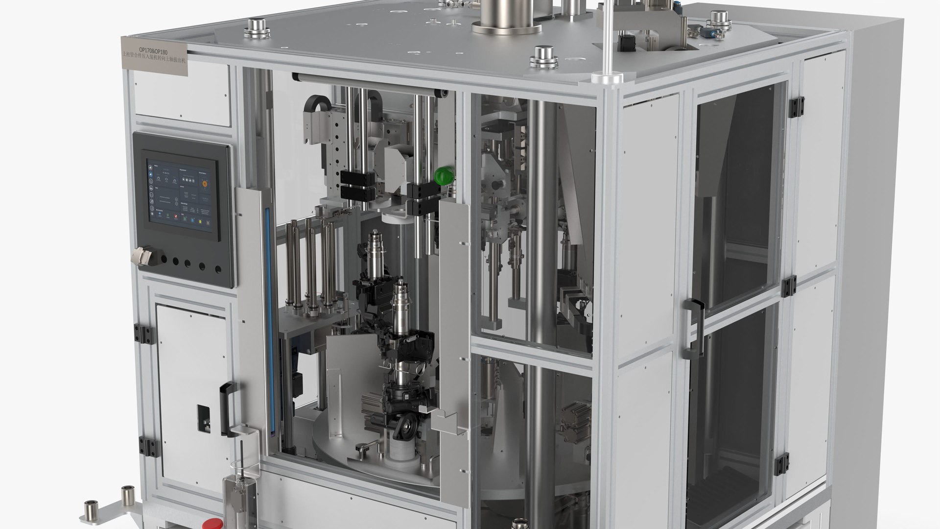
STA3 (13s)
1. The buffer pad grabbing mechanism puts the buffer pad on the steering shaft (6s)
2. The cylinder presses down to press the buffer pad into place (5s)
3. The camera detects whether the buffer pad is pressed in place (2s)
STA4 (23s)
1. The upper string transfer mechanism moves the upper string to the bottom of the servo press (automatically 2s)
2. The lower support mechanism extends to support the lower clamp (1s)
3. The servo press presses down to place the upper string Press into the string assembly (11s)
4. The positioning support mechanism of the lower clamp is retracted (2s)
5. The servo press is retracted to the initial position (3s)
6. The upper string transfer mechanism moves the upper string to STA1 (4s)
STA5 (24s)
1. The servo electric cylinder is lowered (2s)
2. Tighten the servo rotation, insert the guide sleeve into the input shaft (2s)
3. The retaining ring feeding mechanism sends a retaining ring to the guide sleeve (7s)
4. Push out the cylinder to release the push Claw (1s)
5. Gripper cylinder clamps the jaw guide sleeve again (1s)
6. Servo electric cylinder rises, pulls the guide sleeve to press the retaining ring into the groove (4s)
7. Tighten the servo rotation, remove the guide sleeve (2s)
8. The servo electric cylinder rises to lift the guide sleeve (2s)
9. The jacking cylinder retracts (2s)
File Formats
- Inventor 2018 | Keyshot 10
- FBX (Filmbox)
- STEP (Standard for the Exchange of Product Data)
- IGES (Initial Graphics Exchange Specification)
- STL (Standard Tessellation Language )
- OBJ (Object Files)
- x_t (Parasolic Model Part File)
Geometry
- Polygons: 12,180,332
- Vertice: 28,343,662